RelaiXedPassive -- audio attenuator
Introduction
The RelaixedPassive is the 3rd member of my RelaiXed designs.
It is an audio volume control and input channel selector with a minimalistic passive design:
there are are no active parts in the audio path: no transistors, opamps, tubes.
It is a true attenuator.
This attenuator design inherits several aspects of my earlier RelaiXed preamplifier designs:
- It uses tiny relays for volume control and input selection.
The volume control provides 64 steps with approximately 1dB step size.
The high-quality relays and resistors provide a superb audio quality maintained over a very long lifetime.
- It uses the same frontpanel PCB as my other RelaiXed designs:
It provides a combined rotary-and-pushbutton switch for manual control,
and provides an IR receiver for remote control (volume, input select, mute, power on/off).
The controller firmware can be easily updated through USB.
- It uses both software control and hardware design enhancements to avoid clicks in the audio signal when adjusting volume.
- The design comes with complete schematics and open source code of the embedded controller software.
The avoidance of clicks is the major improvement with respect to my original attenuator design
of several years back.
The main difference with the RelaiXed preamp is of course its passive nature,
and the use of standard (single-ended, cinch connected) audio as opposed to a balanced (XLR) design.
This attenuator specifically targets integration in the same cabinet with some power amplifier of your own choice.
Integration with a power amplifier avoids longer cinch cables and connectors at the output of the attenuator.
Due to the relatively high output resistance of a passive volume control,
passive attenuators in general are sensitive to cable quality and cable type.
Integration with the power amplifier removes this sensitivity.
To take further benefit from the IR remote control in the amplifier integration,
this design comes with a full-fledged power switch control with soft-start functionality.
Through a heavy power relay and strong power resistors, the soft-start mode supports the safe switching
of large toroid transformers and/or large capacitor banks in your power supply.
On-board fuses for the control and the mains power output and the little on-board transformer
simplify the wiring in your amplifier chassis.
Design information
-
The hardware design files with schematics and PCB layout with sizes:
Schematics and PCB 20140809. This includes the original front-PCB of the earlier relaixed design.
-
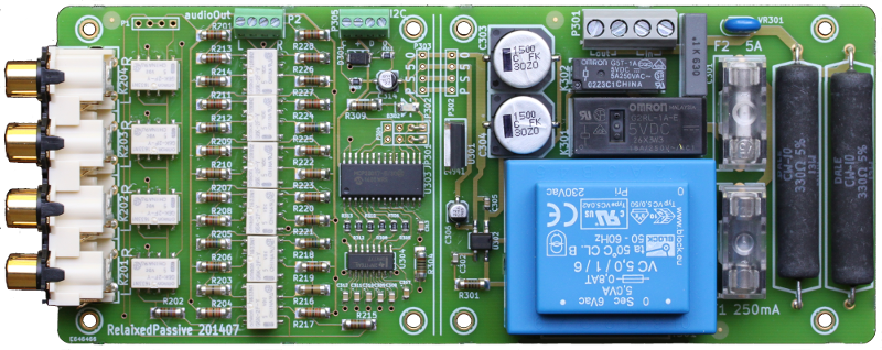
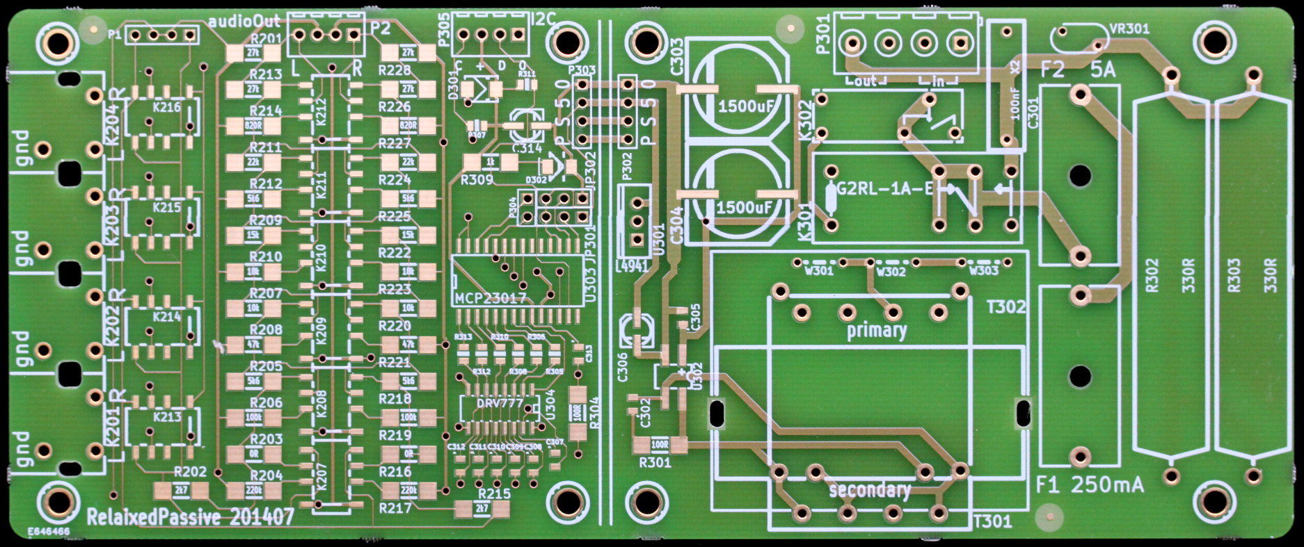
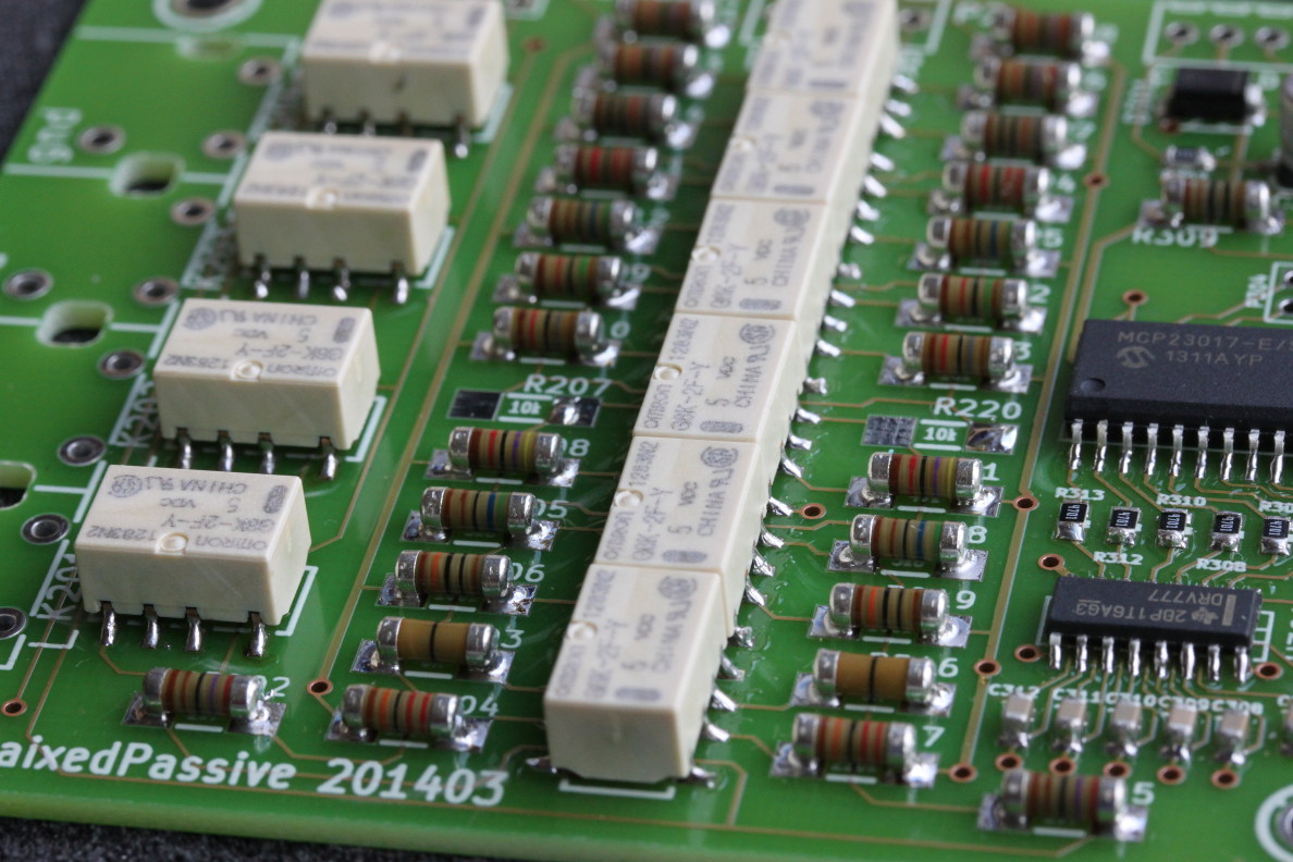
Photo of the empty PCB,
and after the first task with mounted SMD components.
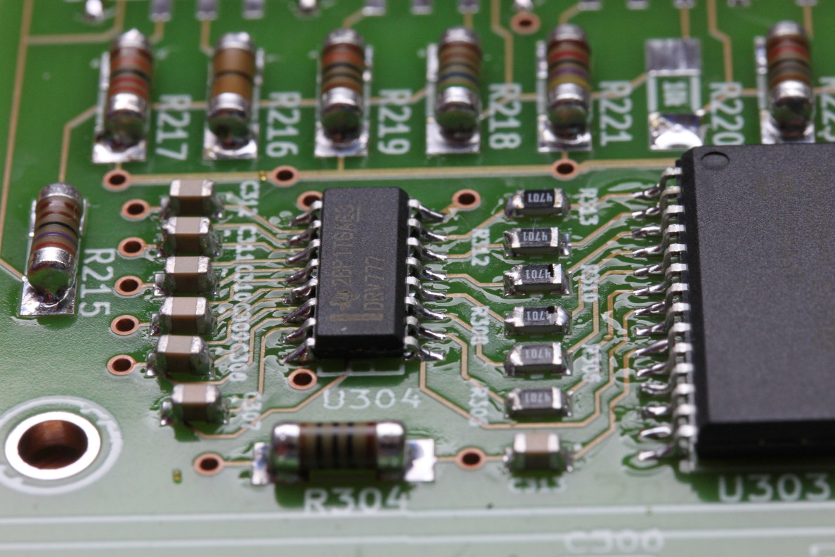
These are close-ups of the SMD
relay-drivers and the
relay mounting.
These are true professional quality PCBs with gold finishing and a thicker-than-default copper layer.
-
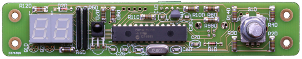
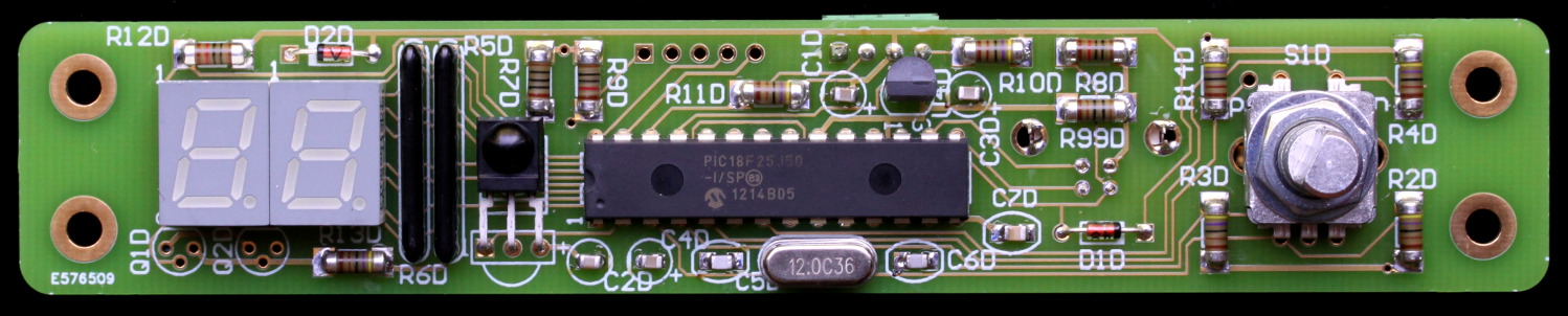
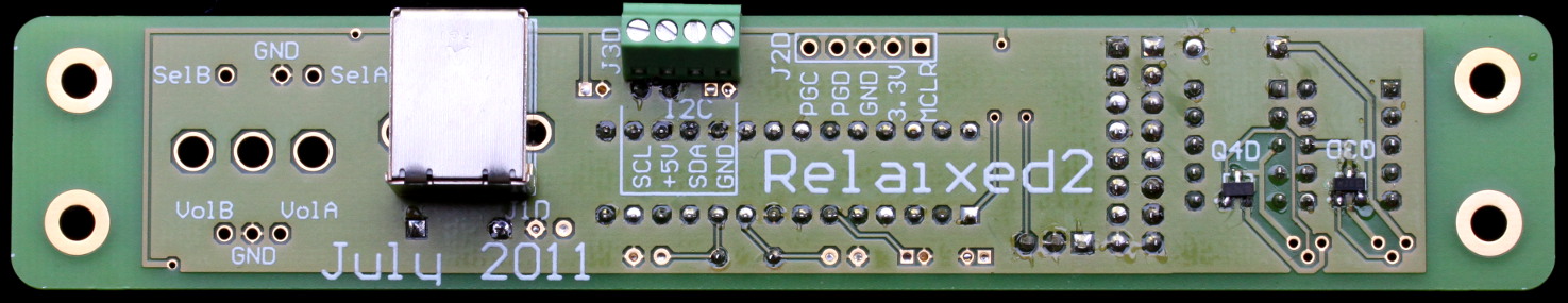
These are photos of the front PCB controller, and its back side.
This controller is to be mounted in the amplifier front panel, and is connected to the main relay board through a 4-wire connection.
Since the relay board is controlled through a standard I2C protocol, some enthousiasts are looking to control my Relaixed relay board(s)
with their own Arduino or raspberry-Pi.
However, I do not provide the software you need for that...
-
Component list and prices (example from Mouser, European prices, excl VAT):
Component table.
-
The online software project,
that provides all source code in a revision control system (svn),
also in a web-browsable format.
The provided source code can be re-built with the free version of the
Microchip MPLAB-X IDE and XC compiler.
If you want to contribute to improving/extending this software, please conact me.
Component availability
The PCBs for this version are not available anymore. Please check out the current revision.
Further design options
Probably most of this text should better move into a real user guide, but for now:
-
With the attenuator resistor values assigned in the schematics, the attenuator has an input resistance of 27K,
and an output resistance that varies between 0 and 13K, depending on the attenuation level.
This value is a compromise between wanting a high input impedance (easy to drive by the signal source)
and a low output impedance (good to drive the power amplifier).
If you would like to change the impedance level (higher or lower) you can find new resistor values
with the help of my online attenuator calculator.
The current values of this design are indicated near the bottom of that page.
-
As is easily seen from the main PCB foto, the PCB can be cut in two separate units: a left half with the audio and some digital
decoding, and a right half with the 5V power-supply and the mains-power switching.
Partitioning the halves allows you some extra freedom in your cabinet layout. Also, if you have doubts of the heavy power switching
so near to the sensitive audio signal, you can place them further apart.
Taking the halves apart, requires a 4-wire low-power link between the two boards.
-
The PCB is designed to allow a
4x2 cinch connector
be mounted on the PCB, which allows for easy assembly without wiring.
Of course, you might alternatively use
high quality single connectors
by wiring these individually to the board, not mounting the example connector block.
-
The front (control) module is the same one as used for the other Relaixed preamp designs. For this passive attenuator,
the embedded software was extended. With the new software, the control board recognizes at power-up time to which type of relay
board it is connected, and adapts accordingly. For instance, this passive board does not offer left-right balance control,
which is available in the full balanced preamplifier.
You should check the
Relaixed user manual
for:
- some instructions on the assembly of this board,
- the use of the IR remote control, and
- (maybe later) upgrading of the software to newer revisions though USB.
-
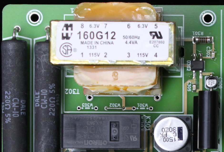
On the right (power) half of the relay board, some component types differ for use in 110/120Vac countries versus 220/240Vac countries.
This is indicated in the compoment table, where the 110V units are indicated as alternative. This holds for:
- the transformer type
- the value of the two power resistors
- the value of the varistor (to suppress voltage spikes)
The blue transformer on the foto is a 230V only device. The component table lists a
transformer from Mouser with a dual primary winding,
which can be used in both voltage domains. For that transformer, the voltage selection van be done with
mounting one or two wires on the PCB to set the proper connections. That should be clear from the schematics,
and this foto with the selection set to 230V.
I assume that in a 120V region, your local component supplier might have alternative types like the blue photo example with a single 120V winding.
Just be careful with studying the transformer footprint...
-
The schematics (and component table) indicate a 5A fuse for the switched mains-power output.
Clearly, you should choose a fuse strength that fits your application load.
In most cases, I guess, that would be a fuse in the range of 3A to 10A, medium speed or slow type.
The selected switch relay is a type that is rated to 16A, and so that is maximum supported by this PCB.
Thanks for your interest,
Jos van Eijndhoven
Please note that these audio developments are just hobby for me, next to very busy job.
These web pages result in many emails to me, which I cannot always answer quickly. So, please, have some patience with me.
I always try to answer within a week...
November 15, 2014